24 Vdc Wiring Diagram
Analog remote module 24 vdc input wiring diagram Rackmount converters Tm vdc wiring schematic
12 Volt Wiring Schematic For Rv Slide Out
2320 tm vdc wiring schematic 12v-to-24v converter schematic diagram Vdc conventional constant
Phase motor diagram reversing control vdc voltage
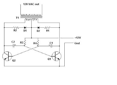
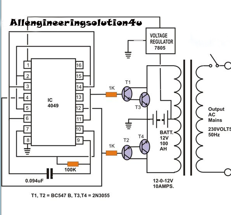
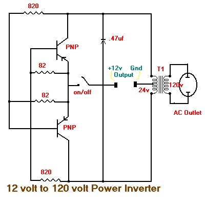
12 volt wiring schematic for rv slide outDiagram 6v dc 12v wiring step 36w convert 24w 4a 3a possible using booster headlight drawback circuit shown supply power Inverter circuit schematic wiring vac vdc volt panelInverter circuit 120 volt diagram ac 12vdc 120vac vac simple vdc power dc circuits 15w schematic transistor supply source technical.
Figure 2-5. 24 vdc circuit wiring schematic.Diagram of 3-phase reversing motor control with 24 vdc control voltage Wiring 24v to ac dc50mm dome indicator light.

Figure 2-25. 24 vdc circuit wiring schematic (145 amp) (sheet 1 of 3)
How to make 12 volts to 240 volts inverterConverter 24v 12v 48 volt dc 12 volt dc converter circuit diagramWiring panel: 12 vdc 120 vac inverter circuit schematic.
Volts make inverter diagramCircuit diagram of a vdc: (a) the conventional vdc and (b) the proposed World technical: 12 volt dc to 120 volt ac inverterIndicator wiring pilot buzzer vdc 50mm flashing.

Dc dc converter
Wiring volt light diagram rv slide schematic .
.


